Get Support
+8801977426642
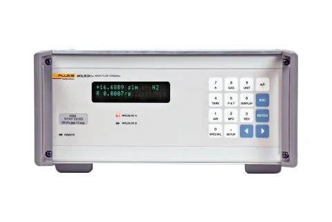
Fluke molbox1+ Flow Terminal
Features at a glance
± 0.125 % of reading uncertainty on mass flow measurements with molbloc-L and molbloc-S elements with premium calibrations
- molbox1+S configuration gives extra rangeability with molbloc-S elements without requiring vacuum pumps
- Now use any molbloc element for both high and low pressure applications in the same gas
- Even more robust internal pneumatic design
- Full suite of software automation products and hardware accessories to create a complete gas flow calibration system—including new COMPASS® for Flow calibration assistance software
Unparalleled uncertainty specifications
molbox1+ innovations enable the molbloc/ molbox1+ system to achieve the lowest gas flow measurement uncertainties in the industry. The lower uncertainty is made possible by several key improvements, including:
- Use of Fluke Calibration's exclusive quartz reference pressure transducer (Q-RPT) technology to precisely measure both absolute and differential pressure. molbox1+ Q-RPTs are specially characterized sensors benefitting from the same technology used in Fluke Calibration’s pressure transfer standards.
- Premium molbloc calibrations linearize molbloc flow output to better capitalize on existing precision and repeatability.
- Expanded molbloc modelization enables improved performance of molbloc-L laminar flow elements across their range of operating pressures.
- Reduced uncertainty on gas properties utilizing data from NIST Reference Fluid Thermodynamic and Transport Properties Database (REFPROP).
- Continued improvements in Fluke Calibration’s molbloc calibration chain, based on fundamental massand time-based mass flow measurements using Fluke Calibration’s own dynamic Gravimetric Flow Standard.
Two levels of molbloc flow element calibration are now available to let you balance uncertainty and cost:
- Premium: ± 0.125 % of reading flow measurement uncertainty (with molbox1+)
- Standard: ± 0.2 % of reading flow measurement uncertainty (with molbox1 or molbox1+)
New molblocs are eligible for either calibration type. Existing molblocs are compatible with molbox1+ at ± 0.2 % of reading uncertainty with no changes required. See below for details on upgrade service to existing molblocs to allow premium calibration and measurement specifications.
The molbloc/molbox system has stood the test of time for flow meter calibration since the early 1990’s, used in many demanding calibration laboratories, intercomparisons and government organizations worldwide. Fluke Calibration’s uncertainty specifications are conservative and backed by a thorough uncertainty analysis and metrology support. Fluke Calibration’s innovation and design is continually aimed at making sure our products deliver specifications that can be realized by the user, not under best case conditions but in your real-world application.
molbox1+S sonic nozzle calibration device expands rangeability—without vacuum pumps molbox1+S is a special configuration of molbox 1+ that enables you to cover a wide range (10:1 range turndown) with molbloc-S sonic nozzle flow elements, without requiring costly vacuum pumps. molbox1+S sonic nozzle calibration device is available with upstream Q-RPT pressure range up to 2 MPa (300 psia) to allow molbloc-S elements to be conveniently used over a wide flow range upstream of flow meters being tested at atmospheric pressure, a common application. This extra rangeability makes it simple to configure a calibration system using fewer molbloc elements and minimal accessories. It also greatly extends the range of your existing molbloc-S elements when a high pressure molbloc calibration is added.
molbloc-S range example with device under test at atmospheric pressure
| Molbloc-S element | Usable range with SP calibration and molbox1 A700K | Usable range with HP calibration and molbox1+S A2M |
| 1E2-S | 15 to 50 slm* | 20 to 200 slm |
| 5E2-S | 67 to 250 slm* | 100 to 1000 slm |
*Minimum usable flow of molbloc-S elements with SP calibrations are limited by back pressure requirements for sonic flow when used upstream of a device at atmospheric pressure. Flow values are in standard liters per minute referenced to 0 °C.
molbox1+S is designed for use with molbloc-S sonic nozzle calibration devices and therefore is configured for absolute pressure measurement only, reducing its cost. It also reduces flow system complexity and overall cost, as well as ongoing recalibration costs.
Use the same molbloc in multiple applications
Multiple molbloc calibrations are now supported for each gas. This means that you can now have a molbloc calibrated separately for use both at high pressure (upstream of the device under test) and low pressure (downstream of the device under test) to support different applications instead of requiring two molblocs or manually loading separate molbloc calibration files. All calibrations are stored on the molbloc EEPROM and the user simply selects the calibration type from the molbox1+ front panel or via molbox1+ remote interface.
COMPASS® for molbox and new COMPASS® for Flow software add automation and more
COMPASS calibration assistance software takes molbloc/molbox to the next step in automating calibrations. COMPASS and a personal computer work with molbloc/molbox to create a modern, full function, turnkey system for calibrating and testing flow devices.
COMPASS sets up device under test (DUT) records (also known as unit under test), defines and associates test procedures with DUTs, runs tests, acquires reference and test data, produces standard and custom calibration reports. Mass flow device gas correction factors and gas density corrections for volumetric devices like rotameters are easily supported, with options to dynamically calculate the corrected flow using automatic input of pressure and temperature measurements. All reference, DUT and test data are collected and stored in standard delimited files that can be easily downloaded to other applications.
A new version of the software, COMPASS for Flow, brings features to flow calibration that were previously only available in Fluke Calibration’s COMPASS for Pressure software. These include:
- Ability to export data to Fluke MET/TRACK® software.
- Enhanced support for devices under test requiring custom calculations on output indications, special communications support and calibration of multiple devices at once.
- Macro support to handle almost unlimited test system automation.
- More complete and flexible support for accessory devices like MFC-CB (DHI mass flow controller control box).
Upgrading is easy
Upgrading from molbox1 to molbox1+ is economical and easy. A hardware and software upgrade can be performed at Fluke Calibration’s Phoenix factory. To upgrade and achieve the new specifications and features offered by molbox1+ the following steps are performed on your system at Fluke Calibration.
- molbox1+ hardware/software changes. Any required parts are changed to make your molbox materially identical to a factory produced molbox1+. The molbox is flashed to v6.0 embedded software. Two options are available: Upgrade your existing molbox1 to meet molbox1+ specificatio ns, or trade up to a new molbox1+, capturing savings by reusing a few key parts.
- Q-RPT characterization of molbox1 internal pressure transducers. Both existing internal pressure transducers are used in the new molbox1+. Extensive characterization of the transducers enhances their precision and ensures they meet molbox1+ specifications.
- molbloc hardware updates. molbloc-L or molbloc-S elements to be used with the molbox1+ require hardware modifications to support the premium uncertainty specification and a new data structure.
- New molbloc gas calibrations. molblocs are fully modeled and calibrated following hardware updates to realize the benefits of the enhanced gas property data used in molbox1+, Fluke Calibration’s improved calibration chain and new molbloc linearization and modeling techniques.
The entire system will be upgraded and returned to you with new specifications and calibration certificates at a fraction of the cost of a new system. Discover the Fluke molbox1+ Flow Terminal price in Bangladesh—accurate, high-performance flow calibration for critical applications.
Key features
- Lowest uncertainty for gas flow calibration at ± 0.125 % of the reading.
- Combined with molbloc-L and molbloc-S flow elements allows for precise calibrations of various flow measurement devices.
- Ideal for calibrating nearly any type of gas flow measurement device within its range of 1 sccm up to 6000 slm.
- Supports use at high pressures, extending the usable flow range.
- Real-time measurements and is supported by traceable calibration in different gases and operating pressures.
Specifications: molbox1+ Flow Terminal
| General specifications | |
| Power requirements | 85 V ac to 264 V ac, 47 Hz to 440 Hz, 18 VA max consumption |
| Normal operating temperature range | 15 °C to 30 °C (59 °F to 86 °F) |
| Storage temperature range | -20 °C to 70 °C (-4 °F to 158 °F) |
| Vibration | Meets MIL-T-28800D |
| Weight | 6.8 kg (15 lb) max |
| Dimensions (WxHxD) | 32 cm x 12 cm x 30 cm (12.6 in x 4.7 in x 11.8 in) approx. |
| Communication ports | RS-232 (COM1), RS-232 (COM2), IEEE-488.2 |
| Pressure connections (molbox1+ and molbloc) | Quick connectors equivalent to Swagelok® QM Series (SS-QM2-B200) |
| Flow ranges | <1 sccm to >5000 slm See separate molbloc-L and molbloc-S range tables |
| Flow measurement rate | 1 second |
| Gases supported (Consult your sales representative for a current list of gases available for factory molbloc calibration.) |
Nitrogen (N2), Air, Argon (Ar), Carbon Monoxide (CO), Helium (He), Oxygen (O2), Carbon Dioxide (CO2), Carbon Tetrafluoride (CF4), Ethane (C2H6), Ethylene (C2H4), Fluoroform (CHF3), Hexafluoroethane (C2F6), Hydrogen (H2), Methane (CH4), Nitrous Oxide (N2O), Propane (C3H8), Sulfur Hexafluoride (SF6), Butane (C4H10), Octafluorocyclobutane (C4F8), Xenon (Xe) |
| Valve driver option | (8) 12 V outputs Each output can sink 500 mA at 12 V, max 1 Amp total |
| MFC control option (analog input/output) | Nominal voltage range: 0 V dc to 6 V dc input 0 V dc to 5 V dc output Nominal current range: 4 mA to 20 mA input 4.01 mA to 20 mA output Accuracy: ± 0.1 % FS (set), ± 0.05 % FS (measure) |
| Pressure measurement | |
| Type | Q-RPT Characterized Quartz Reference Pressure Transducers –Oscillating quartz crystal with mechanical bellows |
| Calibrated pressure range (full scale) | A700K: 0 to 600 kPa absolute (0 to 87 psia) A350K: 0 to 300 kPa absolute (0 to 44 psia) S A1.4M (molbloc-S only): 0 to 1.2 MPa absolute (0 to 174 psia) S A2M (molbloc-S only): 0 to 2 MPa absolute (0 to 290 psia) |
| Measurement uncertainty (one-year) | Absolute pressure4 ± (0.01 % of reading or 0.003 % Q-RPT span, whichever is greater) Differential pressure (A700K with Tare) ± (8.4 Pa (0.0012 psi) or 0.032 % ΔP, whichever is greater) Differential pressure (A350K with Tare) ± (4.2 Pa (0.0006 psi) or 0.026 % ΔP, whichever is greater) |
| Temperature measurement | |
| Type | molbloc PRTs with molbox1+ Ohmic Measurement System |
| Range (FS) | 0 to 40 °C |
| Resolution | 0.01 °C |
| molbloc PRT precision | ± 0.02 °C (15 to 30 ˚C) |
| On-board | Reference resistor 100 and 110 Ω ± 0.01 %, stability < 25 ppm/year Ohmic measurement ± 0.02 % of reading (15 °C to 30 °C) |
| Flow measurement | ||
| With molbloc-L laminar flow elements | ||
| Standard molbloc calibration | Premium molbloc calibration | |
| Range | 0 to 100 % molbloc full scale | 0 to 100 % molbloc full scale |
| Resolution | 0.0015 % FS | 0.0015 % FS |
| Precision1 | ± 0.07 % of reading, ± 0.007 % FS under 10 % FS |
± 0.07 % of reading, ± 0.007 % FS under 10 % FS |
| Stability (one-year)2 | ± 0.09 % of reading, ± 0.009 % FS under 10 % FS |
± 0.03 % of reading, ± 0.003 % FS under 10 % FS |
| Measurement uncertainty3 (For any gas for which the molbloc in use is calibrated) |
± 0.2 % of reading, ± 0.02 % FS under 10 % FS |
± 0.125 % of reading, ± 0.0125 % FS under 10 % FS |
| With molbloc-S sonic nozzle flow elements | ||
| Standard molbloc calibration | Premium molbloc calibration | |
| Range | 10 % to 100 % molbloc full scale | 10 % to 100 % molbloc full scale |
| Resolution | 0.0015 % FS | 0.0015 % FS |
| Precision1 | ± 0.06 % of reading | ± 0.06 % of reading |
| Stability (one-year)2 | ± 0.05 % of reading | ± 0.03 % of reading |
| Measurement uncertainty3 (For any gas for which the molbloc in use is calibrated) |
± 0.2 % of reading | ± 0.125 % of reading4 |
1 Precision: Combined linearity, hysteresis, repeatability.
2 Stability: Maximum change in zero and span over specified time period for typical molbox and molbloc used under typical conditions. As stability can only be predicted, stability for a specific molbox and molbloc should be established from experience.
3 Measurement uncertainty: Maximum deviation of the molbox1+ flow indication from the true value of the flow through the molbloc including precision, stability and Fluke Calibration. For a complete description of uncertainties see technical note 2011TN06B UNCERTAINTY ANALYSIS FOR FLOW MEASURED BY molbloc-L AND molbloc-S MASS FLOW TRANSFER STANDARDS.
4 With regular use of Autozero. Add 0.005 % of Q-RPT span for one year without use of AutoZero, (translates to 0.005 % FS for molbloc-S, does not significantly affect molbloc-S standard calibration or molbloc-L uncertainty.)
All uncertainty specifications reported at k=2