Get Support
+8801977426642
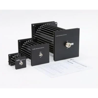
Fluke A40B Series Precision DC and AC Current Shunts
- Simplifies calibration/verification of precision calibrators and current sources
- Shunts sized for currents from 1mA to 100A
- Usable from DC to 100 kHz
- 14 individual DC and AC shunts with a 1, 2, 5 sequence over 6 decades of current
- Simple direct measurements, making ac/dc transfers unnecessary
- Stability is typically better than ± 5.0 µΩ/Ω for one year
- Typical angular accuracy of better than ± 0.003º at 1 kHz
Application
The wide range of shunt values permits measuring from 0.1 mA to 100 Amps. The physical construction and the components used in the current shunts ensure that the frequency response is very flat (amplitude displacement error relative to dc resistance). Also the phase displacement at 100 kHz is small enough to be neglected in all but the highest accuracy measurements. Combined with excellent dc resistance stability, the shunts can be used to directly measure current through their full bandwidth. This simplifies precision ac current measurements as the complex AC/DC transfer measurement process will no longer be necessary for many precision current measurement applications. These characteristics make the A40B shunts ideal for traditional precision current applications such as calibrator verification. Also, the wide current range allows verification of high current transconductance amplifiers. The low phase shift error is critical for the measurement of non-sinusoidal wave shapes, as found in power quality or sampling digital wattmeter measurement applications.
Technical overview
The shunts come in four different sizes. The full current shunt set includes:
- Four fully enclosed dc and ac current shunts: 1 mA, 10 mA, 20 mA, 50 mA
- Five small size radial DC and ac current shunts: 100 mA, 200 mA, 500 mA, 1 A, 2 A
- three medium-sized radial DC and ac current shunts: 5A, 10A, 20A
- Two large-size radial DC and ac current shunts: 50 A, 100 A
Voltage output is nominally 0.8 volts for the nominal rated current input. The output is measured by a voltmeter or detector, such as precision voltmeters, ac measurement standards, ac/dc transfer standards, or thermal voltage converters, fitting them to a wide variety of metrology applications.
The radial style dc and ac current shunt design gives high performance with minimum external magnetic fields. Plus, the open nature of the dc and AC shunt physical design maximizes air flow so the shunts have minimal power coefficient effects. This permits each shunt to be used over a wide range of currents with stable resistance characteristics.
The DC and AC shunt resistance is designed to minimize interaction with the detector instrumentation. The 100 Amp shunt resistance is 8 milliohms, with shunt resistance increasing to 80 ohms for the 10-mA shunt. Additionally, the 1mA shunt includes an internal battery-operated buffer amplifier. It drives the output voltage, so the 800 ohm shunt resistance has minimal interaction with the measurement device.
Reports of calibration
The A40B series of precision DC and AC Current Shunts comes with an ISO 17025 Accredited Certificate of Calibration.
Key Features: Fluke A40B Series Precision DC and AC Current Shunts
- Comprehensive kit with 14 low-inductance coaxial current shunts, adapters, connectors, and a rugged transit/storage case.
- Designed for currents ranging from 1 mA to 100A, intended for laboratory use in making directly measured absolute AC or DC current measurements as well as AC/DC current transfer meaurements.
- Excellent resistance value stability, a superior self-heating power coefficient, and a low temperature coefficient.
- Direct current measurement from DC to 100 kHz with a higher accuracy than previous commercially available shunt technology.
- Precision measurements in a single step process, simplifying the traditional AC/DC transfer methods.
Specifications: A40B Series Precision DC and AC Current Shunts
Basic Electrical Specification Summary
| Shunt Nominal Current |
Nominal Resistance (Ohms) |
Basic Specification ±μA/A, TCal ±1 °C, ≤50 % RH | ||||
| DC | 1 kHz | 10 kHz | 30 kHz | 100 kHz | ||
| 1 mA | 800 | 20 | 55 | 75 | 75 | 150 |
| 10 mA | 80 | 20 | 26 | 26 | 26 | 26 |
| 20 mA | 40 | 20 | 26 | 26 | 26 | 26 |
| 50 mA | 16 | 20 | 23 | 23 | 23 | 23 |
| 100 mA | 8 | 20 | 24 | 24 | 24 | 24 |
| 200 mA | 4 | 20 | 26 | 26 | 26 | 26 |
| 500 mA | 1.6 | 21 | 27 | 27 | 27 | 28 |
| 1 A | 0.8 | 21 | 27 | 28 | 28 | 31 |
| 2 A | 0.4 | 21 | 27 | 30 | 30 | 48 |
| 5 A | 0.16 | 21 | 31 | 32 | 40 | 71 |
| 10 A | 0.08 | 26 | 37 | 60 | 61 | 92 |
| 20 A | 0.04 | 26 | 43 | 52 | 70 | 113 |
| 50 A | 0.016 | 32 | 55 | 80 | 81 | 144 |
| 100 A | 0.008 | 35 | 65 | 90 | 98 | 174 |
Maximum AC-DC Difference
| Shunt Nominal Current: | Maximum AC-DC Difference (± ppm)1,2 | |
| 1 kHz | 100 kHz | |
| 1 mA3 | 53 | 150 |
| 10 mA | 20 | 40 |
| 20 mA | 18 | 30 |
| 50 mA | 13 | 16 |
| 100 mA | 14 | 27 |
| 200 mA | 17 | 28 |
| 500 mA | 17 | 21 |
| 1 A | 17 | 23 |
| 2 A | 17 | 44 |
| 5 A | 23 | 69 |
| 10 A | 28 | 98 |
| 20 A | 37 | 150 |
| 50 A | 47 | 180 |
| 100 A | 60 | 300 |
| 1 Specifications indicate the maximum flatness deviation from dc, and include both measured AC-DC difference and the uncertainty of measurement. They are stated at k=2, approximately 95 % confidence. 2 Includes 1-year stability of the AC-DC difference. 3 Specifications for the 1 mA current shunt are for TCal ± 1 °C. |
||
| General Specifications | |
| Calibration Documentation | 17025 accredited report of calibration included |
| Dimensions (maximum) | Shunt Value: 1 mA to 2 A Height: 70 mm (2.75 in) Width: 70 mm (2.75 in) Overall Length1: 124 mm (4.9 in) Shunt Value: 5 A to 20 A Height: 130 mm (5 in) Width: 130 mm (5 in) Overall Length1: 210 mm (8.25 in)) Shunt Value: 50 A and 100 A Height: 200 mm (7.9 in) Width: 200 mm (7.9 in) Overall Length1: 343 mm (13.5 in)) 1 Includes input and output connectors; subject to change by component vendor. |
| Physical/mechanical parameters | Shunt Value: 1 mA to 20 A Weight: 0.7 kg (1.6 lb) Input Connector: Type-N (female) Output Connector: Type-N (female) Shunt Value: 50 A and 100 A Weight: 3.4 kg (7.5 lb) Input Connector: Type-LC (female) Output Connector: Type-N (female) |
| Operating environment | Temperature: 13 °C to 33 °C Calibration temperature (TCal) range: 18 °C to 28 °C Humidity range for best specification 1,2: ≤ 50 % RH Altitude: 0 m to 3,000 m 1 Resistance stability is affected by humidity, but changes are reversible. 2 If the shunts are calibrated outside this RH, stability specifications will be met as long as the shunts are stored and used at the same relative humidity ± 10 % RH. |
| Storage and transit environments (for models other than the 1 mA current shunt) | Temperature to avoid damage: -20 °C to 140 °C Temperature and humidity to maintain performance1: 5 °C to 45 °C; 15 % to 80 % RH Non-operating altitude: 0 m to 12,000 m 1 Storage at extremes of temperature or humidity will cause a temporary change of shunt resistance by up to ± 20 ppm. When subsequently stored or used within the limits of the operating environment, the shunts will recover to their original resistance value within 30 days. |
| Additional 1 mA current shunt specifications | |
| Output resistance | 8 mΩ |
| Maximum safe output current | 11 mA (e.g., 1 V output into 90 Ω) |
| Maximum capacitive load | 800 pF |
| Output voltage regulation | 15 ppm/100 pF |
| Maximum output dc v offset | ± 100 μV (typical ± 25 μV) |
| Typical error @ 1 MHz | < 2 % |
| Battery specifications | |
| Battery size | AAA (44.5 mm x 10.5 mm) |
| Battery technology | Nickel-Metal Hydride (NiMH) |
| Number of batteries required | 8 (in 2 groups of 4) |
| Nominal battery voltage | 1.2 V (4.8 V per group of 4) |
| Typical battery capacity | 800 mAh |
| Storage and transit environment to preserve the batteries | Less than 90 days: -20 °C to 40 °C Less than one year: -20 °C to 30 °C Charging time (from fully discharged): 100 minutes |
| Maximum operating time between charges | Maximum output load (11 mA): 18 hours High impedance load: 24 hours Recommended cooling period: 100 minutes To prevent loss of battery capacity recharge at least twice per year. |